
Maker Station equipment

3D
printers

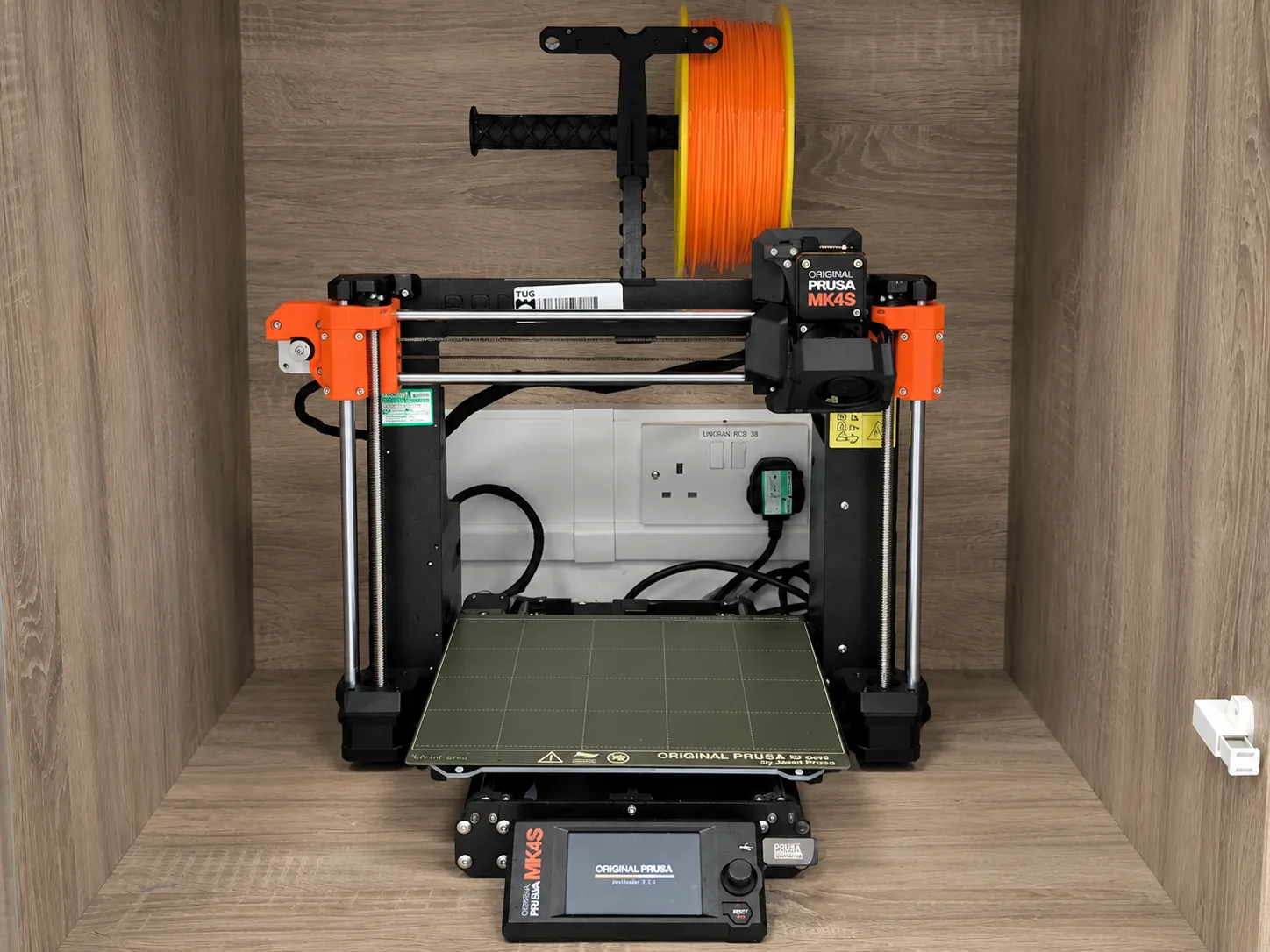
Prusa MK4 FDM printers that build plastic parts layer by layer from sliced 3D models.
← All equipment

A Prusa MK4 3D printer at the Maker Station

Training and hours

3D printing and 3D scanning are taught together as one route of two three-hour sessions. You must complete both sessions. View the workshop route.

Complete the relevant workshop route before booking a 3D printer.

Once you have completed every session in the route you can book a printer through SISO and use it for your own projects.

The station uses Prusa MK4 printers.

Workflow

  1. Inspect the model. Confirm units, dimensions, mesh integrity, minimum features and licence.
  2. Choose orientation. Balance strength, surface quality, stability, supports and print time.
  3. Select local profiles. Match the Prusa MK4, fitted nozzle and station PLA profile in PrusaSlicer.
  4. Set process choices. Use the local starting profile, then make only justified layer, wall, infill and support changes.
  5. Slice and preview. Inspect every layer for unsupported areas, gaps, unexpected toolpaths and support access.
  6. Save the project. Keep a 3MF project with the model, orientation and settings as well as the machine file.
  7. Prepare with staff. Follow the local bed, filament, transfer and pre-print procedure.
  8. Stay with the print until the first layer has finished. Confirm that the complete first layer adheres cleanly. A detached or poorly adhered first layer can produce a large accumulation of loose filament around the bed and nozzle. Follow the station procedure before leaving a print to continue unattended or overnight.
  9. Remove and finish. Wait for the bed and removable spring-steel sheet to cool. Lift the sheet from the printer and flex it gently to release the part, then return it flat and clean the area.

Prepare, slice and preview

Design the part for printing

Design for 3D-Printing by Rahix is the recommended in-depth guide to orientation, strength, tolerances, supports, clearances and designing features around the FDM process.

Prefer 3MF for projects

3MF can retain units, multiple parts, orientation and slicer settings. STL stores only surface geometry and can lose unit context.

Prepare the model

Layer direction affects strength and finish. Thin walls, steep overhangs, tiny details and exact fits need deliberate testing.

  • Confirm the model is a closed volume without accidental internal surfaces.
  • Measure critical features and verify import units instead of scaling by eye.
  • Place the strongest layer direction across expected loads where practical.
  • Split complex work when doing so reduces risky supports or improves orientation.
  • Print a small fit or detail test before committing to a long final print.

Slice and preview

The printer, filament and print profiles work together. A plausible-looking toolpath can still be wrong for the selected machine. Check the preview for:

  • First-layer footprint and bed contact
  • Unsupported islands and bridges
  • Perimeters around thin features and holes
  • Support placement and whether it can be removed
  • Unexpected gaps, missing features or toolpaths outside the model
  • Material estimate and total duration

Choose an infill pattern

Infill supports the internal space of a print and gives top surfaces something to bridge over. More infill does not automatically make a part stronger: orientation, walls and perimeters, material, layer adhesion and geometry all matter.

These ratings are a qualitative selection guide derived from Prusa's infill pattern guide, not engineering test data. Higher means more of the named property: for print speed, higher means faster; for material saving, higher means less material used.

Pattern photographs are from the same guide and remain the property of Prusa Research.

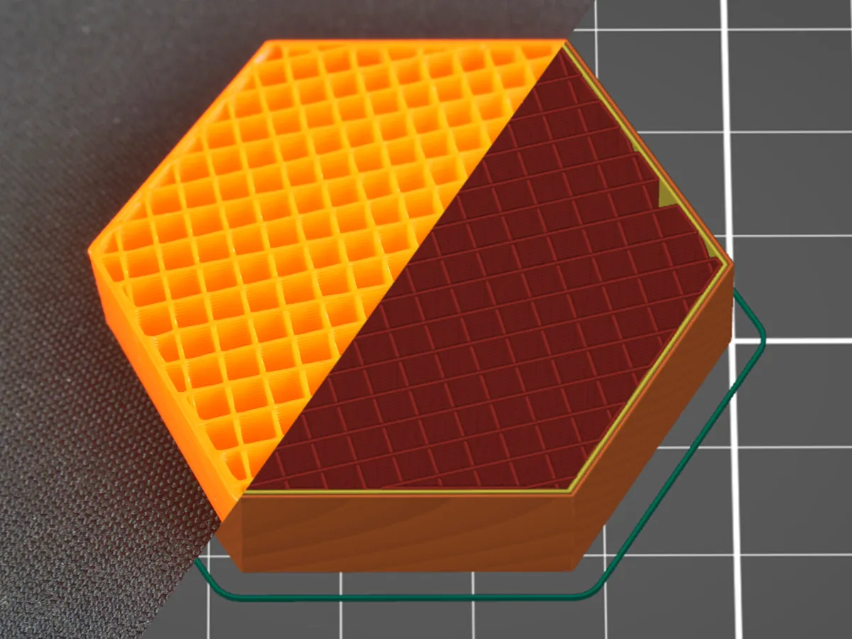
Test block printed with rectilinear infill, shown half as the printed part and half as a slicer preview

Rectilinear

Best forFast general-purpose infill

Lines alternate by 90 degrees between layers, avoiding same-layer crossing buildup and giving strong top support per material. It is the only recommended option at 100% infill.
Print speed
5 out of 55/5
Material saving
4 out of 54/5
XY strength
3 out of 53/5
Multi-direction strength
3 out of 53/5
Top support
5 out of 55/5
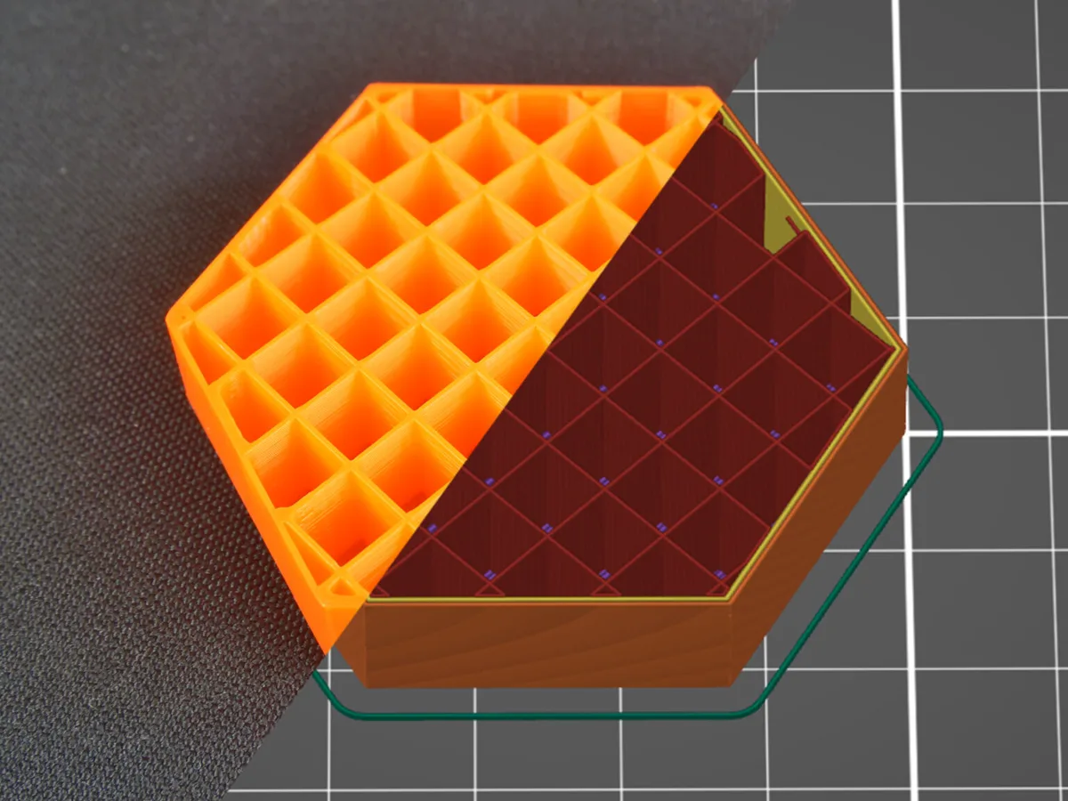
Test block printed with grid infill, shown half as the printed part and half as a slicer preview

Grid

Best forA fast, solid lattice

Both perpendicular directions print in every layer. Material can accumulate at their crossings, creating a risk that the nozzle strikes the raised points.
Print speed
4 out of 54/5
Material saving
3 out of 53/5
XY strength
4 out of 54/5
Multi-direction strength
3 out of 53/5
Top support
2 out of 52/5
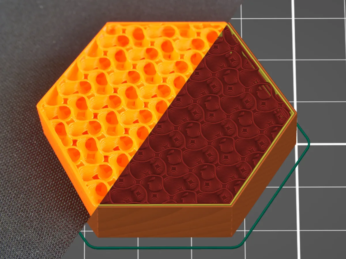
Test block printed with gyroid infill, shown half as the printed part and half as a slicer preview

Gyroid

Best forBalanced strength in every direction

A continuous 3D structure with good strength-to-weight performance. Its curved toolpath does not self-intersect within a single layer.
Print speed
4 out of 54/5
Material saving
4 out of 54/5
XY strength
5 out of 55/5
Multi-direction strength
5 out of 55/5
Top support
4 out of 54/5
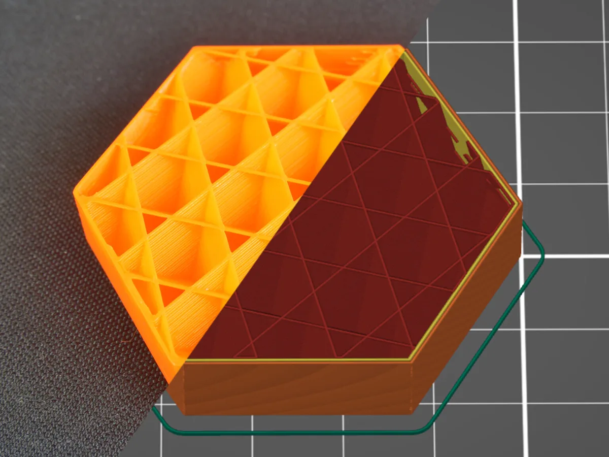
Test block printed with cubic infill, shown half as the printed part and half as a slicer preview

Cubic

Best forEnclosed air pockets

Corner-down cubes create enclosed air pockets, which can be useful when exploring insulation or flotation applications.
Print speed
3 out of 53/5
Material saving
3 out of 53/5
XY strength
3 out of 53/5
Multi-direction strength
3 out of 53/5
Top support
3 out of 53/5
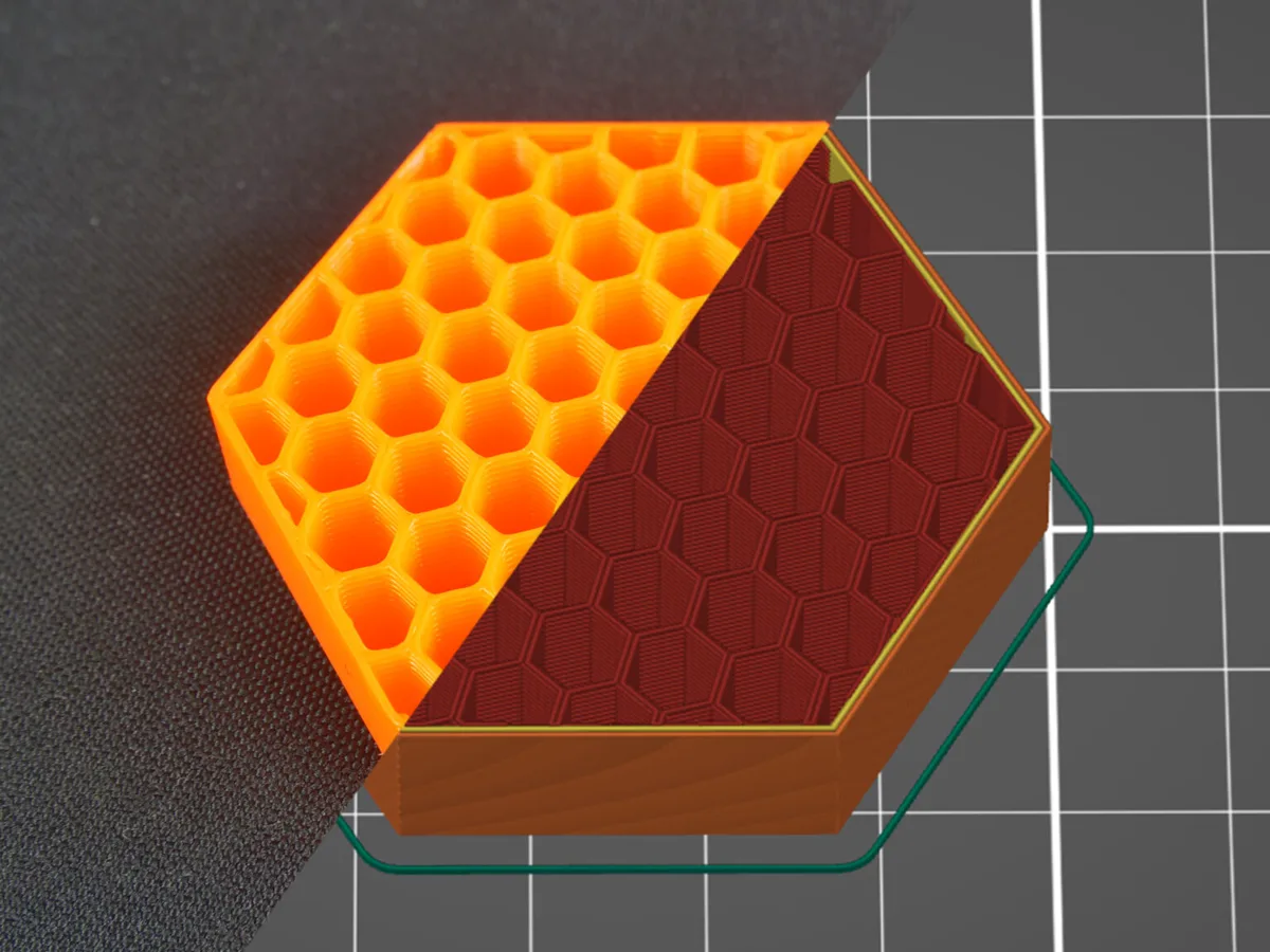
Test block printed with honeycomb infill, shown half as the printed part and half as a slicer preview

Honeycomb

Best forMaximum mechanical resistance

A hexagonal grid with no crossing paths within a layer. Mechanical resistance is its main advantage, paid for with roughly 25% more material and up to twice the print time of the faster patterns.
Print speed
1 out of 51/5
Material saving
1 out of 51/5
XY strength
5 out of 55/5
Multi-direction strength
4 out of 54/5
Top support
4 out of 54/5
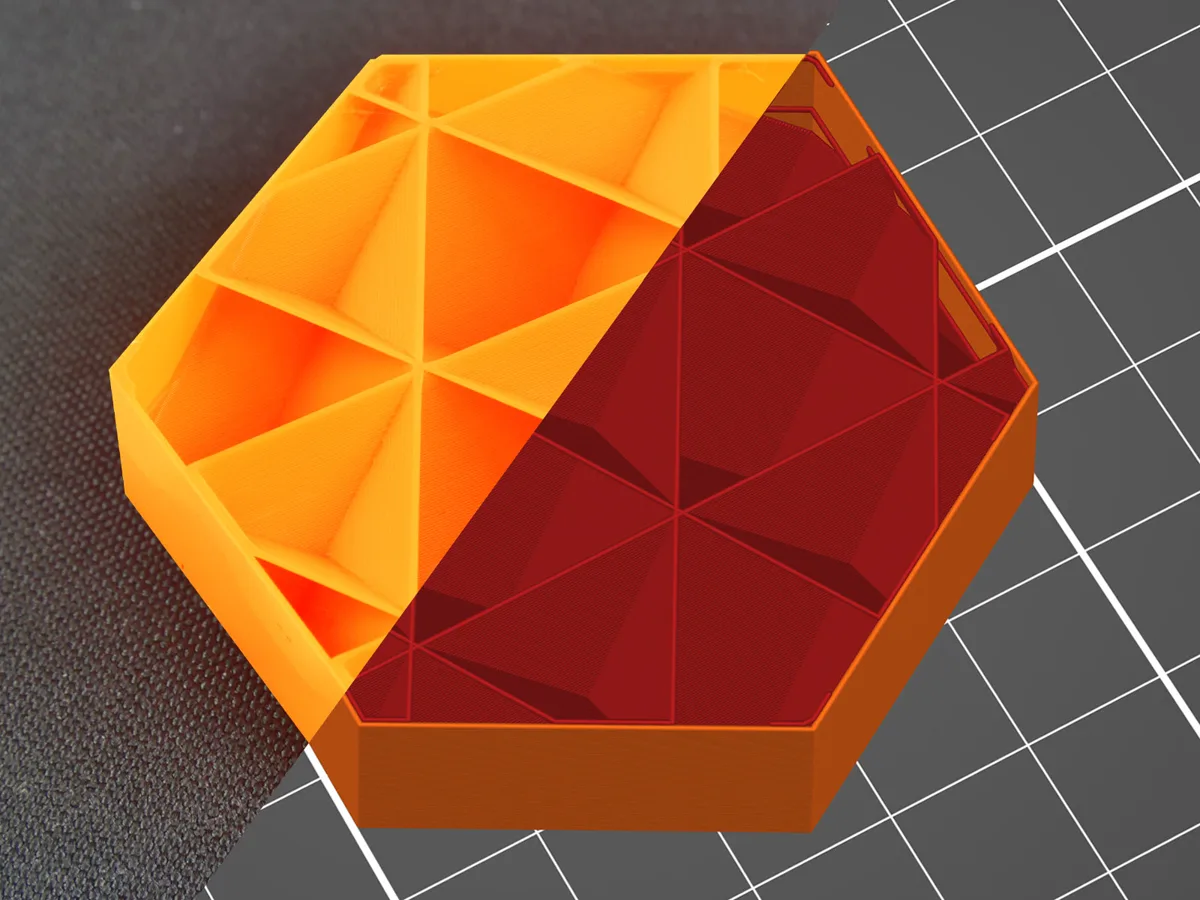
Test block printed with support cubic infill, shown half as the printed part and half as a slicer preview

Support Cubic

Best forFast top-layer support

Density increases toward top surfaces along Z to support upper layers with little material. It does not improve mechanical qualities.
Print speed
5 out of 55/5
Material saving
5 out of 55/5
XY strength
1 out of 51/5
Multi-direction strength
1 out of 51/5
Top support
5 out of 55/5
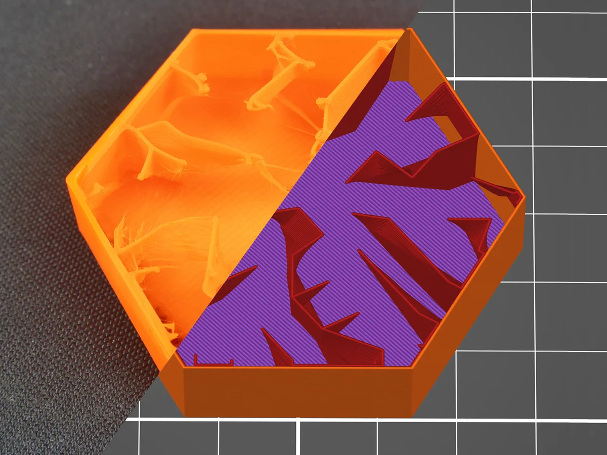
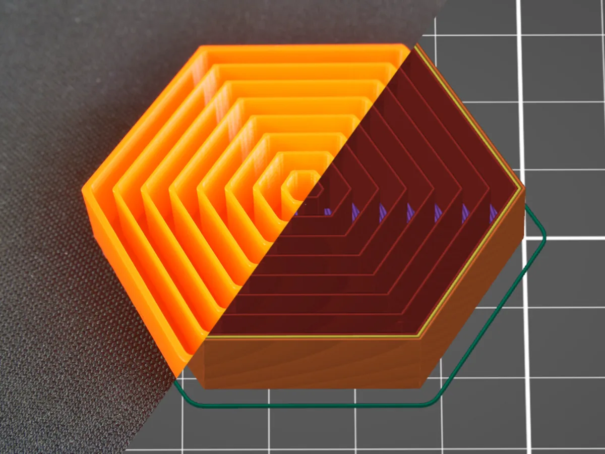
Test block printed with lightning infill, shown half as the printed part and half as a slicer preview

Lightning

Best forDisplay parts using minimum material

Branches form only where needed beneath upper surfaces. This material-efficient support pattern is not structural infill.
Print speed
5 out of 55/5
Material saving
5 out of 55/5
XY strength
1 out of 51/5
Multi-direction strength
1 out of 51/5
Top support
4 out of 54/5
Test block printed with concentric infill, shown half as the printed part and half as a slicer preview

Concentric

Best forFlexible and shape-following parts

Toolpaths follow the outer contours, useful for flexible or transparent work, but the pattern has a slow print time.

Print speed
1 out of 51/5
Material saving
3 out of 53/5
XY strength
2 out of 52/5
Multi-direction strength
1 out of 51/5
Top support
3 out of 53/5

Filament

The Maker Station supplies 1.75 mm PLA for college work, subject to fair use and available stock. Discuss unusually large jobs with staff first.

PLA is the introductory material because it prints reliably at relatively low temperatures, adheres well to the prepared build sheet and has low warping compared with many other common filaments.

The other materials below are included for comparison. They are not currently offered for general use at the station and must not be loaded without staff approval, a compatible printer profile and the required bed, nozzle and ventilation setup.

Common filament families

Station material

PLA

Polylactic acid. Easy to print, dimensionally stable and suitable for models, prototypes and many general-purpose parts. It softens at comparatively low temperatures and is not ideal for hot environments.

Reference

PETG

A tougher, more temperature-resistant material than PLA. It can string, absorbs moisture and needs the correct build-sheet preparation because excessive adhesion can damage some surfaces.

Reference

ABS

A durable engineering plastic that shrinks as it cools. Reliable printing normally requires controlled temperature, an enclosure and suitable ventilation for emissions.

Reference

Flexible TPU

A rubber-like thermoplastic polyurethane. It prints slowly and requires a compatible feed path and profile because soft filament can buckle during loading and extrusion.

Recycled, bio-based and filled filaments

Alternative material

Recycled PLA or PETG

Made partly or fully from recovered polymer. Print behaviour and consistency depend on the feedstock and manufacturer; recycled content does not by itself make a filament locally recyclable.

Alternative material

Wood-filled PLA

PLA compounded with fine wood particles. It produces a wood-like surface but can clog small nozzles and may be more abrasive than standard PLA.

Alternative material

Algae-filled biopolymer

A brand-specific blend using algae-derived or algae-filled content with a polymer carrier. Composition, nozzle requirements and end-of-life claims must be checked for the exact product.

Alternative material

PHA or PLA/PHA

Bio-based polymer filament sold either alone or blended with PLA. Print settings and biodegradability vary by formulation and disposal environment.

Do not load without staff approval

  • Any filament other than the station-supplied PLA
  • Unknown, unlabelled or incorrectly sized filament
  • Abrasive, fibre-filled, metal-filled, wood-filled or glow filament
  • Flexible, high-temperature, support or soluble materials
  • Pellets, fragments, bottle strips or other improvised feedstock

Use the temperature and cooling values in the verified local profile. Values printed on a spool or published online do not confirm compatibility with the installed nozzle, build sheet or ventilation.

Safety

Hot and moving parts

The nozzle and print bed can cause burns, while axes and fans can trap fingers, hair, jewellery or clothing. Keep clear while the printer is heating, homing or moving.

  • Use only a trained and booked printer with the station PLA and approved profile.
  • Do not reach into a moving printer or defeat a guard, enclosure or interlock.
  • Let the bed and removable sheet cool before removing a print.
  • Stop and alert staff for unusual noise, smell, smoke, filament buildup or repeated collisions.
  • Do not service the hotend, change a nozzle or clear a jam unless specifically authorised.

Troubleshooting

Why will the first layer not stick?

Stop early rather than allowing a filament buildup. Ask staff to check the selected profile, bed condition, plate seating, first-layer setup and material. Do not change calibration values by guesswork.

What should I do if the print fails mid-job?

Pause or stop using the trained procedure and alert staff. Keep clear of the hotend and do not pull molten material from a hot or moving nozzle. Keep the failed part and project file for diagnosis.

Why will the supports not come off?

Return to the model and orientation. Consider rotating or splitting the part, changing support placement with staff guidance, or redesigning unsupported features.

Why does the model slice with missing walls?

Check wall thickness, mesh errors and feature size. Repair the source geometry where possible instead of relying on an unexplained automatic fix.

Resources

Model repositories, conversion and generator tools, slicers, textures, AI model generators and video tutorials.

Frequently asked questions

Do I need to know 3D modelling?

No. You can start from an existing model from one of the repositories on the resources page, but you are responsible for checking the licence and that the model is printable.

How long does a print take?

This depends on size, layer height, infill and geometry. The slicer gives an estimate once the model is prepared. Allow additional time for setup and the first-layer check.